Fabric molds could bring material-saving concrete beams within reach
MIT News ·
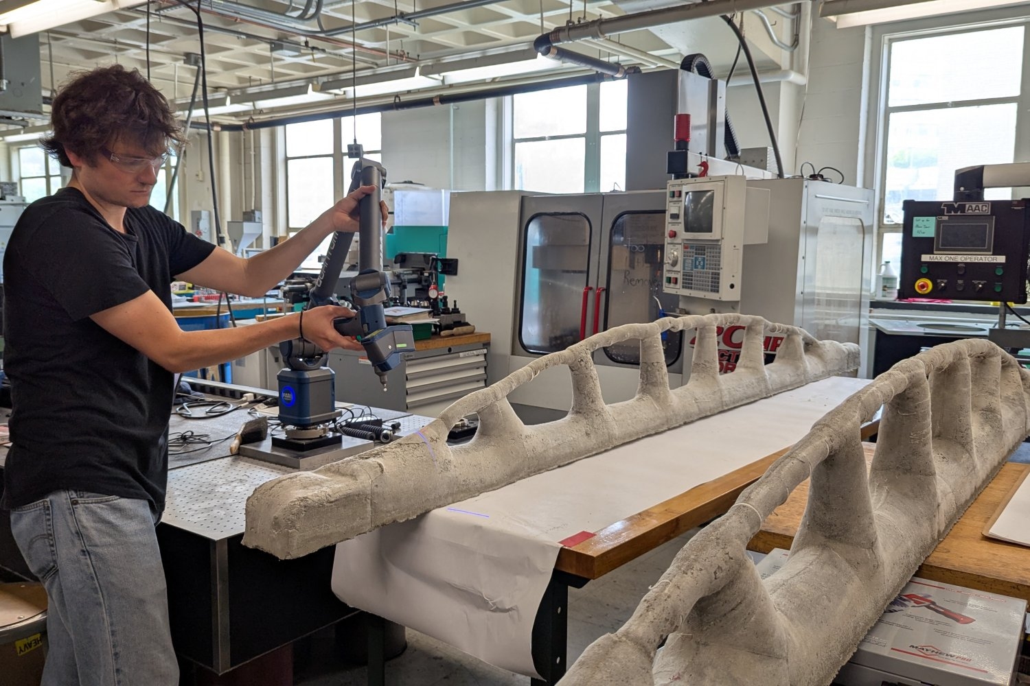
MIT engineers cast a concrete beam using a sewn fabric mold with one-third the amount of concrete and half as much steel as a conventional beam.
Topology optimization is a computer design method that can help engineers design beams using reduced amounts of concrete and steel. But those intricate shapes produced from the tool are often too complex or expensive to pour into conventional rigid molds. The few that have been built have mostly relied on specialized equipment, such as concrete 3D printers or machine-carved molds, equipment that is out of reach in regions where new construction is expected to grow.
Now, MIT engineers have shown that highly efficient beams can be cast in something more accessible: sewn fabric. In a paper published in the Journal of Building Engineering , the team designed and built a 3-meter (about 10-foot) test beam using fabric molds created through an automated pattern-making process. Compared with a conventional beam designed to carry the same weight, the optimized beam used about one-third as much concrete and half as much steel reinforcement. When tested, its measured response was within about 2 percent of what the team's computer model predicted.
Fabric formwork, in which concrete is poured into a mold made of textile, has been explored for years to create beams that vary in depth, rather than in rectangular shapes common in construction. But because fabric deforms under the weight of wet concrete, that flexibility has made the final shape hard to predict.
“The key realization was that this flexibility is not just a limitation to manage; with the right computational pattern design, it can become a way to produce optimized structural forms,” says Josephine Carstensen, the Gilbert W. Winslow (1937) Career Development Professor in Civil Engineering and senior author of the study.
Fabric molds can also be inexpensive, lightweight, and fast compared to wood or steel molds. “You could sew a formwork together off site, pack it into a box, and bring it to a job site very easily,” says Jackson Jewett PhD ’25, co-author of the study. “We joke that we are developing the H&M of the construction industry.”
Less material, lower carbon
Cement production accounts for roughly 8 percent of human-caused carbon emissions.
“This work addresses concrete’s climate footprint primarily by reducing material demand,” Carstensen says. “Cement production is highly carbon-intensive, so using less concrete is an important part of decarbonizing construction.”
Where new construction happens matters, too. The world’s number of buildings is expected to nearly double by 2050, with about 85 percent of that growth in developing countries, where access to advanced construction equipment is often limited. That is why, Carstensen says, the team focused on an accessible, cost-conscious fabrication approach.
Designing the beam
Concrete is strong when compressed, but weak when pulled, so it’s reinforced with steel that can handle the pulling forces. The researchers first mapped a path for the steel reinforcement using a method called graphic statics, which can generate structural designs almost instantly. They used it to shape the steel bar so that it carries an equal share of the weight along its entire length to keep the reinforcement simple enough for builders to make. Topology optimization, which works more slowly but can place material freely, was used to determine where concrete was needed and where material could be removed from areas where it contributes little to the structural performance.
“Both methods are good at different things, so we tried to combine the strengths of both into a single methodology,” says Jewett.
The resulting beam has a top section, narrow angled legs, and a thin bottom section for the steel reinforcement. The team’s automated process translated the 3D beam design into flat fabric pieces that can be cut and sewn into a mold, accounting for how the fabric will deform once concrete is poured in. A simple timber frame supported the finished fabric mold.
Watching the beam take shape
For Mark Hellrich SM ’26, the study’s lead author, the main hands-on challenge was getting the concrete mix right. Woven cotton fabric lets water seep through, so a mix that is too runny loses water through the mold. It also presses harder against the fabric, pushing it away from the intended shape.
The team used a moderately wet, sand-rich mix with only small stones, so the concrete could flow through the beam’s narrow, angled legs and thin bottom section without getting stuck. They then packed it in by hand, prodding each layer and tapping and kneading the fabric from the outside.
“This is where the flexibility of the mold becomes an advantage: you can work the concrete through the interconnected passages without a vibrator, which a rigid mold of this shape would need,” says Hellrich. A concrete vibrator is a tool typically used to shake air pockets out of freshly poured concrete in rigid molds.
Once the concrete was in place, the wet fabric revealed the beam’s final shape. “All three beams were free of wrinkles and creases,” says Hellrich. The top surface stayed close to the design, while the main difference was a downward sag along the bottom, with the angled legs folding slightly inward.
Finding the right fabric mold
To find out how much sewing precision the beam needs, the team built three molds for the same design, made from 36, 56, and 76 fabric pieces. Comparing the 3D scans of the cast beams with the target design, the researchers found that more seams gave finer control over the details, but did not necessarily make the beam’s overall shape more accurate.
“More seams improve local control because they divide the fabric into smaller, more constrained panels. But a more complex pattern also has more pieces to align and more seam length, so small cutting, sewing, and assembly inaccuracies can accumulate across the mold, explains Carstensen.
The 56-piece mold demonstrated the best balance, capturing the important design geometry without the added time, effort, and potential errors associated with the most complex pattern.
The researchers then load-tested one of the beams, gradually stacking 36 water-filled buckets on top of it, up to about 30 percent of its design load to reflect everyday service conditions. Weighted lines hung from the beam’s underside to precise measuring gauges below, tracking how far the beam bent as the load was added and removed. At the beam’s center, the measured deflection — its downward movement under the load — was within about 2 percent of the computer model’s prediction.
Where it fits in the real world
The team also compared the cost of a single fabric-formed beam with a conventional one and found that location makes all the difference. In the Global South, where materials tend to cost more relative to labor, all three fabric versions were cheaper, with savings of about 10 to 20 percent. In the Global North, higher labor costs for sewing reversed that advantage, making the fabric versions about 16 to 55 percent more expensive.
The findings suggest that fabric formwork is most promising for custom-shaped concrete components produced as a one-off or in small batches, such as exposed beams, roof or long-span framing, pedestrian structures, and landscape elements. For the repetitive, rectangular beams found in most buildings, conventional reusable molds remain the more economical choice where labor is expensive.
“To get started, a builder would need the digital pattern for the target component, a sewing machine and suitable fabric, and a simple timber support frame,” Carstensen says. “That is a much lower equipment threshold than robotic fabrication, concrete 3D printing, or CNC-milled molds.”
The researchers describe the 3-meter beam as a proof of concept comparable to a short building span. It is also a big step up from the 1.2-meter beam the team built in a previous project, Jewett notes.
Building bigger isn’t just a matter of enlarging the design, Carstensen notes. As a beam gets longer, its own weight and the pressure on the fabric mold change, so a larger beam would need a new design. The next step, Carstensen says, is “to test multiple beams to failure.”
“The nice thing about these optimization methods is they generate structures that look organic,” Jewett says. “Their geometries are clear expressions of how the forces move through the structural system. There is elegance to them. It makes you ask why we don’t design all our structures in this way.”
Joining Carstensen, Jewett, and Hellrich on the paper are co-authors Abhinit Sati, Edward Chien, and Emily Whiting, of Boston University’s Department of Computer Science.
The work was partially supported by the U.S. National Science Foundation.